BEC Automation › Products › Altus Nexto Jet I/O System
NJ6010
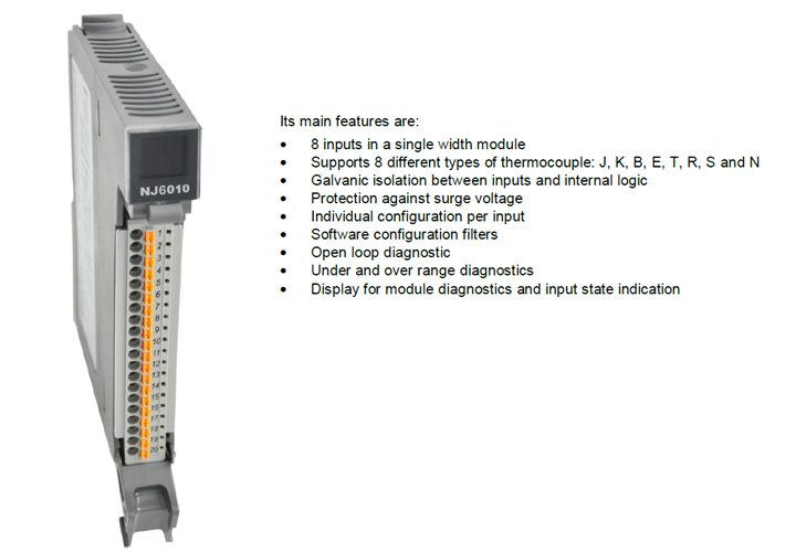
8 AI Thermocouple Module
Key specifications
- 8 AI Thermocouple Module NJ6010 Nexto Series
- In this context, Nexto Jet is a selection of I/O modules that uses the existing CPUs and modules from Nexto Series to provide the best solution for applications in verticals like infrastructure, building, water, wastewater, food, machines and
- several OEM projects. Nexto Jet is ideal for systems with no hot-swapping and conformal coating requirements. Finally the module NJ6010 has eight thermocouple analog inputs which can be individually configured to different kinds of
- thermocouple. Also, this module provides different temperature scales either in Celsius or Fahrenheit. Besides, due to its configurable filters, it also can be used in automation processes, where both low pass filter and notch filter are c ommonly
- 8 inputs in a single width module Supports 8 different types of thermocouple: J, K, B, E, T, R, S and N
- Individual configuration per input Software configuration filters
- Code Description NJ6010 8 AI Thermocouple Module
- Backplane rack occupation 1 slot Number of inputs 8 analog inputs
- Input type Thermocouple, type: J, K, B, E, T, R, S and N Input state indication Yes
- Status and diagnostic indication Display, web pages and CPU’s internal memory Hot swap capability No
- IEC 61131-2 CE, Electromagnetic Compatibility directives (EMC) and Low-
- Altus S.A. 4 Thermocouple Mode Features
- NJ6010 – Thermocouple Mode Temperature drift 0.001 % /°C of full scale rating
- Open thermocouple detection Indicated in the diagnostics Cold junction compensation Compensation range 0 to 80 °C
- 60 Hz 542 ms Thermocouple mode: °C
- -150 a 1300 ºC 0.08% Thermocouple mode: °F
- Maximum conversion time: The conversion time shown in the table above refers to the total conversion time for the 8 channels according to the selected noise suppression filter.
- Accuracy: The informed accuracy is in percentage of the maximum temperature value of each thermocouple type. Example: For thermocouple type R in the range 0 to 200 ºC the percentage error is 0.14% of the 1768 ºC maximum
- represents a feed-through terminal block with connection to other terminal block. 2 – Input 00 is connected to a thermocouple sensor, placed on the field. The cable shielding of this input is connected to
- the grounding terminal block. 3 – Input 02 is connected to a thermocouple sensor, placed on the field. The cable shielding of this input and input 03 is